NEWS

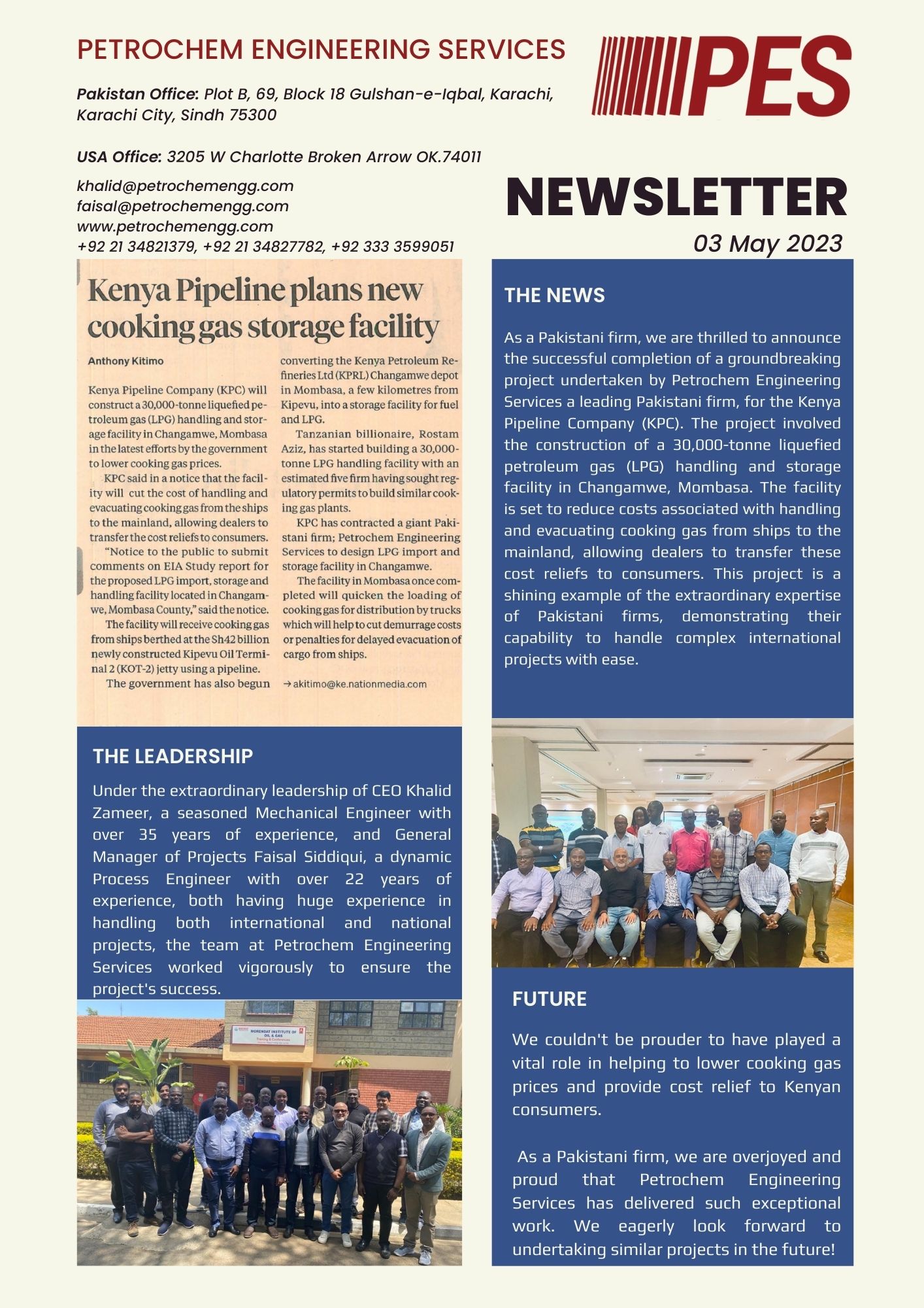
“Latest Accomplishment: Front End Engineering Design for 30,000 mT LPG Storage Facility and 5.2 Km Pipeline Completed!”
We are thrilled to announce the successful completion of a groundbreaking project. The project was undertaken by Petrochem Engineering Services for the Kenya Pipeline Company (KPC) of a 30,000-tonne liquefied petroleum gas (LPG) handling and storage facility in Changamwe, Mombasa. Under the extraordinary leadership of CEO Khalid Zameer and General Manager Projects Faisal Siddiqui, the team at Petrochem Engineering Services worked vigorously to ensure the project’s success. Both have extensive experience in handling international and national projects, thus demonstrating their capability to easily handle complex international projects.
This project is a shining example of the extraordinary expertise of Pakistani firms, showcasing our capability to deliver successful results on international platforms. In constructing the facility, interest was given to cost reduction in handling and evacuating cooking gas which will, in turn, allow dealers to transfer these cost reliefs to consumers. The successful outcome of this project has enabled us to play a vital role in helping reduce cooking gas prices and providing cost relief to Kenyan consumers. Additionally, the project will ensure quicker loading of cooking gas for distribution, thus reducing penalties for delayed delivery of cargo from ships.
As a Pakistani firm, we are overjoyed and proud that Petrochem Engineering Services has delivered such exceptional work. We strongly believe that this will inspire you to take up with us challenging projects locally and as well internationally.

The PROCESS Column
FALL 2018 Newsletter
- PROJECT SPOTLIGHTS
- Process Now Offering Computational Fluid Dynamics Modeling
- Polymer Pilot Plant Detail Design
- TECHNICAL DISCUSSION – Beware API vs ASME: Relief Valve Orifice Size
- SAFETY PAUSE – Routine Operations – It Could Happen to You
PROJECT SPOTLIGHTS
PROCESS NOW OFFERING COMPUTATIONAL FLUID DYNAMICS MODELING
CFD modeling provides time-accurate, three-dimensional insights into fluid motion, reaction chemistry, particle trajectories, heat transfer, and free surface dynamics. The development of new fluid modeling algorithms, combined with modern computational architectures, now enable engineers to simulate the performance of fluid handling equipment with a fidelity that rivals what can be measured experimentally. Just a few examples of where we can use CFD:

- Multi-Phase Newtonian and Non-Newtonian Fluids
- Mixed Tanks (Agitator Performance, Reactant or Impurity Concentrations, Impact of Internals)
- Piping (flow profile, flashing liquids, slurries)
- Heat transfer
- Chemical Reactions
- and much much more
POLYMER PILOT PLANT DETAIL DESIGN
Process Engineering Associates, LLC (PROCESS) was contracted by the client, a specialty polymers manufacturer, to provide continued project engineering support during the detail design / build phases of their polymer pilot-plant project. The purpose of PROCESS’ effort was to provide value-added consultation and process engineering support to both the client and the engineering company that is providing detail design, procurement, and construction management of the polymer plant. PROCESS’involvement spanned the detail design phase of the project up to and including the final Pre-Startup Process Hazards Analysis (PHA).

Many are not aware of the major differences between the orifice sizes and discharge coefficients suggested by the API and the actual, ASME values used by the relief valve vendors. According to API-520, Part 1, the API orifice sizes and discharge coefficients are assumed values and are to be used only for the initial selection of the relief valve. They were developed to facilitate choosing a relief valve size early in a project and to ensure that the relief valve finally purchased will have a certified capacity that meets or exceeds the required relief capacity.

However, the differences in capacity between the initial choice of API orifice and the actual ASME orifice can be significant. For most projects, the actual ASME orifice can provide a much greater flowrate. When one also considers the following:
Conservatisms in estimating the required relief loads;
Calculated orifice sizes are usually between the standard, letter designated API sizes. When this occurs, the next larger orifice size is chosen resulting in the valve being oversized with just an API orifice;
The certified ASME discharge coefficient is derated by a factor of 0.9 resulting in another potential source of over design; the final, purchased, relief valve can be greatly oversized.
The attached table, compares just the differences between orifice designs for two relief valves versus an initial, API design. The first column is the API letter designation for the orifice, followed by the API and then the ASME orifice areas in the next two columns. The fourth column shows that, just based on orifice size, except for the “T” orifice, the ASME orifice flow area is about 16% higher than the API area.
TAKE A PAUSE FOR SAFETY
Routine operations are sometimes the most dangerous because we become complacent about them. Don’t believe it? This story involves an old wastewater treatment system that utilized 98% sulfuric acid which was pumped from a storage tank directly into the process.

PROCESS extends our, prayers, thoughts, and best wishes to those affected by Hurricane Florence and the catastrophic events that have followed. We express our sincere appreciation to the emergency workers and volunteers who are working to maintain the safety of those in the communities. PROCESS supports our many clients, colleagues, and friends along the East Coast as they journey to a safe restart of their respective facilities and put the pieces of their lives back together


